An Architectural System for Architects using AutoCAD and Sketchup
Over the years as Practicing as Grant Lucas Architect I have developed my own CAD documentation system. This Documentation system is systematic, but also has flexibility, allowing me to tweak it a little whenever required. Importantly it is also very portable and easy to implement. My system is two staged, assuming for the first stage that the user already has a good to excellent knowledge of AutoCAD, and for the second that they are moderately competent with Sketchup. The first stage can be used stand-alone, and due to the accuracy, speed and small size of Autocad files it still forms the basis for all of my 2d detailing.
Download free files to My Autocad Documentation System here
1234.dwg This is my plan template
5678.dwg This is my section and Elevation template
AA_clean.dwg This is a clean drawing with basic layers for editing blocks not created with this system before inserting them into my template
MCA1.ctb This is the plot style table for pen thicknesses. (Refer to Autocad Documentation for how to implement)
Additional Autocad blocks compliant to my system (files of basic building elements) will be regularly added, so bookmark my website and come back to check for updates.
Architectural Training to Increase Skill Levels and Employment
Architectural training places heavy emphasis on Design skills, but not so much on the essential skills a Graduate Architect will need to perform once they are cut free of the protective University environment and trying to find employment. We are taught how to appreciate Art and critically analyse Derrida and Foucault, but not how to prepare a decent set of Working drawings. Sadly, understanding the thoughts of French Postmodernists may make for a well rounded Liberal arts education, but it isn’t going to find you work in an Architectural office.Read MoreAs an Architect near the end of my Career I have the dubious advantage of being able to look back and make comment on how the demise of ink on tracing paper drawing and the rise of CAD (and then subsequently BIM) has made pursuing a career as a Practicing Architect more difficult.
I began my professional career by contracting to local Architectural firms before I became a CAD manager, stepping up from firm to firm before I went out on my own. I have now come full circle and as one of the Principals of an Architectural Office now need to assess the capability of young graduates. What do I look at to asses an applicants suitability? It isn’t enough to look at a printed set of Documents, you also need to see how they are constructed. A good set of CAD drawings is no longer just lines but a data base full of intelligent information that should be easily understood by the next person opening up the drawing.
If you are a graduate Architect looking to gain employment then read on, as I will endeavor to explain how my small Architectural Practice documents both Residential extensions and New homes.
Architectural Documentation: Moving from 2D to 3D
After joining the workforce I soon found out the truth….if you could produce a great set of documents you could find work anywhere.Read MoreEmployers don’t worry about qualifications they only want results. If you can make them money they will employ you. If you cannot, then you will need to find another Profession. Good CAD drafting relies on having a good system. If you are not systematic then re-use is difficult. A good system will make every drawing you do part of a growing portfolio of detailing that you can re-use from job to job. This saves time as well as allowing for more accurate detailing, which in turn avoids construction problems. All of this is good for employment prospects.
When I learned AutoCAD I had to teach myself, as the University of Adelaide refused to teach it. CAD was mainly left in the domain of Tech schools and TAFE as Computer Aided Drafting was considered a trade rather than an intellectual pursuit. My Lecturers actually boasted that they were above both CAD drafting and design Detailing and that “on the job training” would take care of this aspect of my development. Little wonder that the Department Of Architecture almost lost accreditation whilst I was there. Ironically as a young Architect I found that gaining a foothold in the industry was only possible because of my CAD knowledge…. self taught and no thanks to my expensive and useless diploma. As for gaining detailing knowledge “on the job”…. everyone was either too busy or protecting their own tenuous existence in a cut-throat industry.
Although I had an excellent system for producing 2D AutoCAD documentation, Clients expectations increased during the “twenty tens”. I found I was now also regularly producing 3d images and walk-throughs in Sketchup to explain my designs. There isn’t a lot of profit in Architecture and since all time is very valuable I adapted my initial AutoCAD system to include re-use of these Sketchup perspectives and Elevations in my Working drawings.
How to Integrate Sketchup into Autocad Documentation
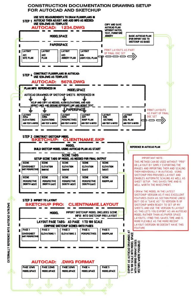
The process of embedding Sketchup information into an Autocad document set requires a reasonably good knowledge of both Autocad and Sketchup. It is however a very useful skill to learn as these hybrid drawings are an excellent way of communicating construction intent to the Client, Builder and Subcontractors. I have drawn a flowchart explaining the basic process below.
Documenting a Composite Set of Sketchup and Autocad Drawings: FLOWCHART
The Addition of Sketchup Data Increases Drawing Comprehension
The addition of Sketchup Elevations, Plans and Perspectives increases my systems complexity considerably, but I have found that although more time is required to document I now use far less iterations. This is because SKETCHUP explains the design intention to my clients so well.I have found that I am now spending about 20% longer on a job than I previously did, but there is now very little abortive work. The designs also now have less problems during construction. This is because the 3d model enables the designer to better think about and resolve every junction, rather than just the ones on major elevations.
A System for AutoCAD Documentation of Residential Architecture
The Basic Autocad System
My basic Autocad Documentation system relies on the use of 2 template AutoCAD drawings.
The essence of the system is that Drawing 1234.dwg (contains layout drawings A01, A02, A03 and A04) is the plan-base drawing which is then reused and referenced into 5678.dwg (contains A05, A06, A07 and A08 layouts) which contains the sections and elevations.
Although this system is specifically for Architectural documentation of Residential buildings and extensions, it can easily be adapted to Commercial buildings as I originally created it for that use. After the GFC I took a break from Commercial work for 5 years and concentrated on my Residential practice. It was during that time I re-developed my system for Residential use on A3 Layouts (Councils in S.A insist on A3 format for Residential submissions)
Accuracy and Efficiency by Plan Re-use
Accuracy is maintained by only putting plan information in one location and then simply using this as a Data base underlay which is accessed as many times as required. Both Paperspace and Model space is used and the space around the drawing margins in both spaces is used to house useful re-usable information such as notes and Blocks. This information can be appended with each subsequent job making the process simpler and more streamlined with time.
A Layer System For AutoCAD Documentation
The Layering system contained within these Template drawings forms the foundation of my approach.
The first template (1234.dwg) is the most important as it contains the underlying plan information which is initially built up from a thorough measured survey of the site and then manipulated to subsequently include demolition information and new works.
Consider Your AutoCAD Drawing as a Database
Because I consider this drawing as a data base and not just lines it is important that all information is drawn on the correct layer and then if it is to be demolished just transferred to a corresponding demolition layer rather than removed. Correspondingly any new building work should be put on its own discrete and descriptive layer. This way no information is lost, everything is clearly understood and any user can easily open up the drawing and determine what is intended without asking any questions.
ISO Standard for Layers
The layer system in these templates is based on what was a world ISO standard for CAD layering back in the early “noughties” when BIM was still fairly unheard of. There are lots of layers, but most can be purged out once the drawing is finished. The way the element layer names are ordered means that by simply freezing and thawing particular arrangements of layer name prefixes it is easy to display New, Demolition and Existing building plan arrangements at the touch of a keystroke. This means that very accurate drawings can be composed at great speed.
Layer Names Based on ISO convention
A typical layer under this system would be A-PARTN-18-CON.
This interprets to Architectural, PARTitioN, pen .18 thickness, CONtinuous linetype.
Use Systematic Layer Name Prefixes to Enable Rapid Layer Sorting
The first few letters of the layer names enable rapid sorting:
A- stands for Architecture
B- stands for services
C- stands for civil
S-stands for structural
N_ appended before any of the disciplines (A-, B-, S-, or C-) is New work for that discipline eg N_A-PARTN-18-CON is a new partition
D- is for demolition. eg D-PARTN is a demolished partition
If you haven’t downloaded my Residential Architectural plan template 1234.dwg yet DOWNLOAD THE TEMPLATE DRAWING NOW and open it in Autocad to see the full layer system. The drawing is saved as Autocad R13 format, so it is useable by those with older versions
Building Element Layer Descriptive
The system requires that the building element portion of the layer is kept to 5 characters. Vowels are removed in preference to consonants for long elemental names which need shortening eg A-WALLS, A-PARTN, C-BNDRY, (boundary)
Pens and Line Thicknesses in Plotted Drawings
The pen thickness system I use is pen plot thickness by standard Autocad colour (with colour by layer). I adhere to the following colour convention system as traditionally many institutions used it. I have kept these colour/thickness relationships as I have constructed many thousands of blocks using this convention.This allows for much re-use and therefore is a huge time-saver. The pen file “mca1.ctb” is the standard for my template drawings and controls the plot thicknesses. This should be placed in the appropriate directory (Refer to Autocad Documentation for this step)
Pen Colour Convention
The colours 250 to 255 are transparent greys’ and can be used to effect in background and mask colours. Eg 255 is the colour of paper & so a solid 255 hatch in the foreground can mask out other lines underneath. The other greys’ are useful for wall shading & background line-work. Pens 1 to 9 are reserved for pen thicknesses and the other colours will print out in their true colour at a .18 thick line. The grey colour 8 is the thinnest line & it plots out at around .1mm thick I have trialed various printers and although many they say that they print down to .07 there is no visible difference below around .1. For this reason my thinnest linetype layer is labelled as .13 thickness, which is a leftover from the past hand drawn system where .13 was the thinnest pitograph ink pen available. You will note that I have allocated blue as the thickest line at .99 not 1.0 as it means that it is in ascending order numerically. Also blue reads out poorly on a black screen & so I use it seldom.
Pen Thickness Descriptives
Grey colour 8 =.1 plot thickness
Magenta colour 6 =.18 plot thickness
White colour 7 =.25 thick
Yellow & green colours 2 & 3 =.35 plot thickness
Red colour 1 =.5 plot thickness
Cyan colour 4 =.7 plot thickness
Blue colour 5 =.99 plot thickness
Colour 251 darkest grey
Colour 252 darker grey
Colour 253 lighter grey
Colour 254 lightest grey
Colour 255 white mask
All other pens are true to colour at .18 thickness.
AutoCAD Linetype Acronym Descriptions
Linetypes have their own 3 letter shortened acronym as part of my layer system nomenclature. The first two letters are for the AutoCAD linetype and the last letter indicates if it is full scale, half scale, or double scale.
CON =continuous line This is the basic linetype
DAF =Dashed full scale
DAH = dashed half scale
DAD =dashed double scale
HIH =hidden half scale
HID =hidden double scale
PHF =Phantom Fullscale
DDH =dash dot Half scale
Adding Sketchup Information into your AutoCAD Drawing
Sketchup Make or Sketchup Pro? Is Pro worth the money?
Is it worth spending the money to buy Sketchup Pro? In short YES! I used my system for over 2 years with the standard Free Sketchup (Sketchup Make). You can still create great looking Documents, but it takes longer. Unlike AutoCAD, Sketcup Pro is relatively cheap. I saved the money Pro cost me on the first job, just with the time saved importing Sketchup Scaled Vector images into Autocad.
Sketchup has a “save scene” feature that is similar to saved views in Autocad. These are saved as easily accessible tabs in the drawing. Each scene can be set up as required for future use. By including the appropriate view settings and using “parallel projection” accurate Elevations and plans can be created. If you have Sketchup PRO, then these can be composed in LAYOUT with hybrid setting on so that vector information is included rather than rasters. This means that when exported into Autocad they are Autocad lines rather than just images. Each elevation can then be accurately aligned and dimensioned just as if the elevation was drawn natively in Autocad.
Exporting Sketchup Scenes from Layout and Importing them into AutoCAD
Can I use any Version of Sketchup Pro?
I Prefer to use an older version of Sketchup Pro (Sketchup 15) to export my layouts to Autocad .DWG format.
Sketchup Pro 15’s Export feature suits my needs best. I still use the latest Sketchup version to create my Model as it has some nice features (like section poche), but before exporting I do a Save-As back to version 15 and I re- name it so it isn’t confused with my version 18 working model. The version 15 lets me save each of my layout pages as an Autocad Drawing with a 1 to 100 composed sheet with Vector lines in Autocad Modelspace. This is an important part of my system as I can then easily import these drawings into my Autocad 5678 drawing in modelspace and compose them just as if they were natively drawn in Autocad. The vectors are accurate and so I can place dimension lines on these imported models.
Finalising the Composite AutoCAD Sketchup drawing set
After Importing the Sketchup generated Autocad pages into my Autocad model (simply an Xref process rather than an import asd they are now Autocad format) I clip and align the elevations on my pre-drawn height lines as required. I then set up my viewports in Paperspace layout tabs and compose the elevations. I add all notes and dimensions in paperspace but may use the chspace command to transfer them directly onto the model below if the composition of the sheet benefits by it.
Learning how to Document Residential Buildings… Where to next?
Download and play with my free template files 1234.dwg and 5678.dwg just to see how the basic system works and familiarise yourself with the system. Just seeing how someone else works is a very helpful learning experience…. even if you don’t decide to use my system it may help you tweak your own system.
If you would like a worked example then also download 5678_example.dwg . Note that all drawings should be placed in one directory so they can reference each other.
Bookmark and come back to my website for more details as I will be regularly expanding on how to use my system, as well as adding plenty of Autocad .dwg Blocks that will make the process easier.
I WISH YOU HAPPY DRAFTING….